Tuesday, November 29, 2016

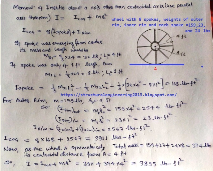
Solved - Moment of Inertia- Spoked Wheel with inner and outer Ring.

Hi,
I was stuck at this problem of finding the mass moment of inertia of a spoked wheel/ring, which is necessary to find out the angular acceleration or the kinetic energy of the wheel.

It's easy to determine the moment of inertia of a spoked wheel with the given weights of the outer rim/ring, inner rim/ring and weight of spokes. The moment of inertia about the centroid and an axis parallel to the centroidal axis can also be easily found. Please refer the image below for knowing the process.


Thanks! please share and subscribe!

Sunday, July 6, 2014

Flexure Stress and Normal Stress

Hello there,

Its a long time since I have posted in my Structural Engineering blog, so today I thought to discuss something in here. If I ask you the type of stresses, you may come up with the following types:

  1. Normal Stress
  2. Shear Stress
  3. Flexure Stress
    Flexure Stress Vs Normal Stress
These are the three types of stresses which we deal all along our structural engineering, arising out of so many different types of loading on the structure. I asked this question to one of my student, if there is any similarity between the first one and the third one. 

Normal stress is calculated simply as Force divided by the cross section area under action. Flexure stress is calculated with the help of the flexure formula. Now, to find out the similarility between the two, you have to consider the nature of them.
We know normal stress are either tensile or compressive, similarly, you know that the flexure stresses are also either tensile or compressive.

The main difference between the two, is that the normal stress remains constant throughout the section, but the flexure stress varies along the cross section. This shows that the similarity between the two is that the flexure stresses are also the normal stresses but with a constant variation along the cross section on which applied. 

Thanks for your kind visit!

Sunday, June 15, 2014

List of Civil Engineering Softwares used these days

Hi, I was going through the online website of the Autodesk and found a list of the softwares, which caught my interest because many of them are new to me. I have worked with the AutoCad and am little aware of Revit, but there is this huge list of the softwares, titled as given below:
  1. Building Design suite
  2. AutoCAD
  3. Revit
  4. Simulation Mechanical
  5. AutoCAD 360
  6. Buzzsaw
  7. Robot Structural Analysis Professional
  8. Vault
  9. Advance Steel
  10. Point Layout
  11. Simulation 360
  12. AutoCAD LT
  13. Advance Concrete
    License page for downloading the trial versions of Autodesk 
Now, if I was in the software industry related with the Civil Engineering projects, hopefully I would have been associated with the other 11 softwares too, but I have ignored them till now. Now that I am thinking of pursuing my M.Tech. in Structural Engineering, I think I should have the knowledge of these softwares. 

I think to learn about all these softwares, you need a lot of free time. At the same time, interest matters a lot. If you are interested, you can go the website and try them for free, and if they fulfill your thirst, you can buy them and yes they are very costly.
What do you think, is it important to have the knowledge of every new software product in the market?

Saturday, March 1, 2014

Welding | Design of Steel Structure

Hi,
Welding is a method in which metals are joined together by melting them. This post discusses fillet weld and slot weld, in brief.

Fillet Welds

  • Size of fillet weld. It should not be less than the minimum allowable value given in the table  in the image above. Size of the fillet weld used along tee of an angle or rounded edge of a flange should not exceed three-forth the nominal thickness of an angle of flange leg.
  • Throat of fillet weld. It is length of perpendicular from right angle corner to the hypotenuse.
Effective throat thickness = k*fillet size
Value of k depends upon angle between fusion faces. Value of k decreases with increase in angle between fusion face.
In most cases, a right angled fillet weld is used, for which k = 0.7.
  • Effective length of fillet weld. It is equal to its overall length minus twice the weld size. Effective length of a fillet weld designed to transmit the loading should not be less than four times weld size. Equal return should be made equal to twice the size of the weld.
  • Overlap. Overlap in lap joint should not be less than five times the thickness of the thinner plate as shown in the figure to right.
  • Side Fillet. In a lap joint made by a side or longitudinal fillet weld, length of each fillet weld should not be less than perpendicular distance between them; the perpendicular distance between side fillets should not exceed sixteen times thickness of the thinner part connected. 
  • Intermittent fillet weld. Any section of an intermittent fillet weld should have an effective length of not less than four time the weld size or 40 mm, whichever is greater. Clear spacing between ends or effective lengths of intermittent weld carrying stresses should not exceed 12.t for compression and 16.t for tension and in no case should be more than 20cm, 't; is the thickness of thinner part joined.
  • Permissible stress and strength of fillet weld. Permissible stress in fillet weld is 108 MPa or 1100 kgf/cm2.
Permissible stresses in shear and tension are reduced to 80% for the fillet welds made during erection. Permissible stresses are increased by 25% if wind or earthquake load are taken into account. However, size of the weld should not be less than the size required when the wind or earthquake load is considered or neglected.

Slot or Plug Weld

Following specifications are used for the design of slot or Plug welds:
  1. Width or diameter of slot should not be less than three times the thickness of the part in which slot is formed or 25 mm, whichever is greater.
  2. Corners at the enclosed ends should be rounded to a radius not less than 1.5 times the thickness of upper plate or 12 mm, whichever is greater.
  3. Distance between edges of the plates and slot or between edges of adjacent slots should not be less than twice the thickness of the upper plate.
  4. Permissible stress is taken as 108 MPa or 1100 kgf/cm2.
Thanks!

Monday, January 20, 2014

Two Way Slabs - IS Codes Specification

Hi,

Indian Standard codes give following specification for two way slabs for their analysis.

  • Case 1: Simply supported slabs which do not have adequate provision to resist torsion at corners, and to prevent the corners from lifting. 

Bending moment for short span,  Mx= Ax.w.Lx^2
Bending moment for long span, My = Ay.w.Ly^2
Where, Ax and Ay are moment co-efficients depending on the ratio Lx/Ly.

  • Case 2. Simply supported on the four edges and corners of the slabs are held down.
If Mx and My are maximum bending moments per unit width in the middle strip of the slab in short and long spans respectively, then
                                                   Mx = Ax.w.Lx^2
                                                  My = Ay.w.Ly^2
Where Ax and Ay are co-efficients depending on the ratio Ly/Lx.
At the corners, top and bottom reinforcement should be provided for torsion.

Thanks for visit!


Wednesday, January 8, 2014

Structure Engineering notes for GATE and PSUs - part 13

Hello there,
How have you been!?

 Here is our next part for your preparation for the GATE and PSUs examinations.
All information is learned through books and practical exercises.


  1. The symmetrical two-hinged parabolic arch when subjected to a uniformly distributed load on the whole span, is subject to normal thrust only.
  2. In a two-hinged arch, an increase in temperature induces a maximum bending moment at the crown.
  3. The normal thrust at any section of the arch is the component of interacting forces on the section along the tangent to the centerline of the arch.
  4. The radial shear at any section of the arch is the component of the interacting forces on the section along the normal to the centerline of the arch.
  5. The intercept between a given arch and the linear arch at a section is proportional to the bending moment at the section.
  6. A fixed beam AB is subjected to a triangular load varying from zero at end A to 'w' per unit length at end B. The ratio of fixed end moment at end B to that at end A is 3/2.
  7. The horizontal thrust due to the rise in temperature in a semi-circular two-hinged arch of radius R is proportional to 1/R2.
Thanks!

Sunday, January 5, 2014

Structure Engineering notes for GATE and PSUs - part 12

Hello there,
How have you been? Here is our next part for your preparation of GATE and PSUs examinations.
All information is learned through books and practical exercises.

  • A T-section is used as a simply supported beam with uniform loading. The maximum bending stress for a given load will occur at the bottom of the section.
  • Mohr's circle becomes zero when the both the axial stresses are equal in magnitude and of same nature and both planes being free from shear.
  • For beams, I-sections are more economical than rectangular sections because most of the material is concentrated away from the centroid.
  • The shear stress distribution over a rectangular cross section of a beam follows a parabolic path.
  • Shear stress distribution diagram varies for different cross sectional shapes.
  • Bending stress distribution diagram is similar for different sections.
  • Polar moment of inertia is sum of MI about the XX and YY axes.
  • A cantilever beam of uniform EI has span equal to 'L'. An upward force W acts at the mid point of the beam and a downward force P acts at the free end. In order that the deflection at the free end is zero, the relation between P and W should be W=16P/5.
  • If K is defined as the ratio of Young's modulus of elasticity and the permissible stress in compression of a material used in the construction of a column, then the Rankine's constant used in finding the load carrying capacity of columns is proportional to 1/K.


Reference:


Thanks for visit!

Saturday, January 4, 2014

Structure Engineering notes for GATE and PSUs - part 11

Hello there,
How have you been? Here is our next part for your preparation of GATE and PSUs examinations.

  • The allowable tensile stress in structural mild steel plates for steel tank is assumed as 105.5 MPa on net area.
  • Steel tanks are mainly designed for water pressure.
  • Box type sections should preferably by used at places where torsion occurs.
  • The capacity of the smallest pressed steel tank is 1950 litres.
  • The bracing between two columns of a steel tanks will be designed to resist horizontal shear due to wind or earthquake + 2.5% of column loads.
  • The minimum thickness of plates in a steel stack should be 6 mm.
  • Maximum pitch of rivets, used in steel stacks, is limited to 10t, where t is the thickness of the thinner plate being connected.
  • The diameter of base of conical flare of a steel stack is more than d, where d is the diameter of the cylindrical part.
  • Hudson's formula gives the dead weight of a truss bridge as a function of bottom chord area.
  • If the loaded length of span in metres of a railway steel bridge carrying a single track is 6m, then impact factor is taken as between 0.5 to 1.0.
  • If the floor is supported at or near the bottom but top chords of a bridge are not braced, then the bridge is called half through bridge.
  • The centrifugal force due to curvature of track is assumed to act on the bridge at a height of 1.83 m above the rail level.
  • The effect of racking forces is considered in the design of lateral braces.
  • When the secondary stresses are taken into account along with primary stresses, then the allowable stress is increased by 96/3%.
  • The portal bracing in a truss bridge is used to transfer load from top of end posts to bearings.
  • The sway bracing is designed to transfer 50% of the top panel wind load to bottom bracing.
  • The bracing provided in the plane of the end posts is called portal bracing.
  • The portal bracing is designed for wind force + 5/4% of the compression force in two end posts.
  • The pin of a rocker bearing in a bridge is designed for bearing, shear and bending.
  • The least dimension in case of a circular column of diameter D is taken as 0.88D.
  • In case of timber structures, the form factor for solid circular cross-section is taken as 1.18.
  • In case of timber structures, the simple bending formula M-f.z may be applied for rectangular beams up to 300 mm depth.
  • The elastic strain of the steel is about 1/12 strain at the initiation of strain hardening and 1/200 of maximum strain.

All information is learned through books and practical exercises.

Reference:


Thanks for visit!

Friday, January 3, 2014

Structure Engineering notes for GATE and PSUs - part 10

Hello there,
How have you been? Here is our next part for your preparation of GATE and PSUs examinations.
  • Half of the main steel in a simply supported slab is bent up near the support at a distance of l/7 from the center of slab bearing.
  • When shear stress exceeds the permissible limit in a slab, then it is reduced by increasing the depth of the beam.
  • If the size of panel in a flat slab is 6m * 6m, then as per Indian Standard Code, the widths of column strip and middle strip are 3.0 m and 3.0 m.
  • For a slab supported on its four edges with corners held down and loaded uniformly, the Marcus correction factor to the moments obtained by Grashoff Rankine's theory is always less than 1. 
  • The permissible diagonal tensile stress in reinforced brick work is about 0.1 N/mm2.
  • The limits of percentage p of the longitudinal reinforcement in a column is given by 0.8% to 6%.
  • The minimum diameter of longitudinal bars in a column is 12 mm.
  • The minimum cover to the ties or spirals should not be less than 25 mm.
  • The load carrying capacity of a helically reinforced column as compared to that of a tied column is about 5% more.
  • The diameter of ties in a column should be more than 5 mm and also more than one-fourth of diameter of main bar.
  • Due to circumferential action of the spiral in a spirally reinforced column both the capacity of the column and ductility of the column increase.
  • For heights beyond 6 m counterfort RC walls are preferred over L and T -shaped walls.
  • For the design of retaining walls, the minimum factor of safety against over-turning is taken as 2.0
All information is learned through books and practical exercises.

Reference:


Thanks for visit!

Wednesday, January 1, 2014

Structure Engineering notes for GATE and PSUs - part 9

Hello there,
How have you been? Here is our next part for your preparation of GATE and PSUs examinations.


  • Strain Energy stored in a member is given by 0.5*Stress*Strain*Volume
  • Two identical bars, one simply supported and other fixed at ends, are acted upon by equal loads applied at the midpoints. The ratio of strain energy stored in the simply supported beam and the fixed ended beam is 4.
  • If the depth of a beam of rectangular section is reduced to half, strain energy stored in the beam becomes 8 times.
  • The specimen in a Charpy impact test is supported as a simply supported beam.
  • Impact test enables one to estimate the property of toughness.
  • The phenomenon of decreased resistance of a material to reversal of stress is called fatigue.
  • The stress below which a material has a high probability of not failing under reversal of stress is known as endurance limit.
  • A three hinged parabolic arch rib is acted upon by a single load at the left quarter point. If the central rise is increased and the shape of arch altered at segmental without changing the other details, the horizontal thrust will decrease definitely.
  • For ductile materials, the most appropriate failure theory is maximum shear stress theory.
  • For the design of a cast iron member, the most appropriate theory of failure is Rankine's theory.
  • Principal plane in a uni-dimensional stress system is defined as the plane where Shear stress is zero and normal stress is maximum.
  • If an element is subjected to pure shearing stress t, the maximum principal stress is equal to t.


Thanks for joining in!

Reference: Google & A book "Civil Engineering Objective" by S P Gupta and S P Gupta.

Tuesday, December 31, 2013

Structure Engineering notes for GATE and PSUs - part 8

Hello there,

Are you ready for next part of our preparation notes, for GATE and other PSU examinations?
Here we go:

  • In the displacement method of structure analysis, the basic unknowns are displacements.
  • The fixed supports in a real beam becomes in the conjugate beam a free end.
  • The width of the analogous column in the method of column analogy is 1/EI.
  • The deformation caused by a unit load in a spring is called the flexibility.
  • Conjugate beam can be used to determine slopes and deflection in a non-prismatic beam and gives absolute slope and deflection.
  • In a three hinged arch maximum horizontal thrust occurs when the unit load is at the crown and maximum sagging moment at a section occurs when the unit load is at the section itself.
  • Influence line diagram for the horizontal thrust in a two hinged parabolic arch is cubic.
  • For a single point load W moving on a symmetrical three hinged parabolic arch of span L, the maximum sagging moment occurs at a distance 0.211L from ends.
  • Muller Breslau's principle for obtaining influence lines is applicable to:
  1. trusses
  2. Statically determinate beams and frames
  3. Statically indeterminate structures, the material of which is elastic and obeys Hooke's law.
  • Due to moving loads, the stress in a web member of a truss is given by the influence line for the bending moment for the node point opposite of the member.
  • The stress in a chord member of a truss is given by influence line of shear force for the panel containing the member.
  • In the cantilever method of lateral load analysis, the intensity of axial stress in each column of a storey is proportional to the horizontal distance of that column from the center of gravity of all columns of the storey under consideration.
  • The factor method of analyzing building frames is based upon the slop-deflection method of analysis and is more accurate than either portal or cantilever method.

Thank you for visiting!

Reference: Civil Engineering objectives by S P Gupta and S P Gupta

Monday, December 30, 2013

Structure Engineering notes for GATE and PSUs - part 7

Hello there,
How have you been? Here is our next part for your preparation of GATE and PSUs examinations.


  • A linear arch has normal thrust only, no shear force and no bending moment.
  • A three hinged parabolic arch containing uniformly distributed load is free from the bending moment and shear force.
  • For a determinate pin jointed plane frame, the relation between the number of joints j and members m is given by,  m=2j-3.
  • Triangle is a basic perfect frame.
  • Method of joints is applicable only when the number of unknown forces at the joint under consideration is not more than two.
  • A hollow shaft will transmit more power than a solid shaft of same weight and material.
  • The stiffness of a helical spring is expressed as load per unit deflection.
  • If a rectangular shaft is subjected to torsion, the maximum shear stress occurs at middle of the longer side.
  • If a circular shaft is subjected to a torque T and bending moment M, the ratio of maximum bending stress and maximum shear stress is  2M/T.
  • The radius of gyration of a circle of radius R is equal to  R/2.
  • The ratio of intensity of stress in case of a suddenly applied load to that in case of a gradually applied load is 1.
Thanks for joining in!

Reference: Google & A book "Civil Engineering Objective" by S P Gupta and S P Gupta.

Sunday, December 29, 2013

Structure Engineering notes for GATE and PSUs - part 6

Hello there,

Are you ready for next part of our preparation notes?
Here we go:


  • According to IS:456: 1978, the column or the strut is the member whose effective length is greater than 4 times the least lateral dimenstion.
  • According to IS:456:1978, minimum slenderness ratio for a short column is less than 12.
  • Lap length in compression shall not be less than 24 times diameter of the bar.
  • The minimum cover in slab should neither be less than diameter of the bar nor less than 15 mm.
  • For a longitudinal reinforcing bar in a column, the minimum cover shall neither be less than diameter of the bar nor less than 40 mm.
  • The ratio of the diameter of the reinforcing bars and slab thickness is 1/8.
  • According to IS:456-1978, the maximum reinforcement in a column in a column is 6%.
  • The percentage of reinforcement in case of slabs, when high strength deformed bars are used is not less than 0.12.
  • Minimum cross sectional area of longitudinal reinforcement  in a column is 0.8%.
  • Spacing of longitudinal bars measured along the periphery of column should not exceed 300 mm.
  • Reinforcing bars in columns should not be less than 12 mm.
  • Higher slump and higher compaction factor shows higher workability.
  • Minimum pitch of transverse reinforcement in a column is lesser of 
  1. the lease lateral dimension of the member
  2. Sixteen times the smallest diameter of the longitudinal reinforcement bar to be tied
  3. forty eight times the diameter of the transverse reinforcement.
  • Maximum distance between expansion joints in structures as per IS:456-1978 is 45 m.
  • A continuous beam is deemed to be a deep beam when the ratio of effective span to overall depth (l/D) is less than 2.5.
  • Critical section for shear in case of flat slabs is at a distance of d/2 from the periphery of column/capital/drop panel.
  • Minimum thickness of load bearing RCC wall should be 100 mm.
  • If the storey height is equal to length of RCC wall, the percentage increase in strength is 10.
  • In reinforced concrete footing on soil, the minimum thickness at edge should not be less than 150 mm.
  • The slab is designed as one way if the ratio of long span to short span is greater than 2.
  • Ratio of permissible stress in direct compression and bending compression is less than 1.
  • A higher modular ratio shows a lower compression strength of concrete.
  • The average permissible stress in bond for plain bars in tension is increased by 25% for bars in compression.
  • In working stress design, permissible bond stress in the case of deformed bars is more than that in plain bars by 40%.
  • The main reason for providing numbers of reinforcing bars at a support in a simply supported beam is to resist in that zone the bond stress.

Thanks for visiting!

Bye!