This blog is dedicated to Structural Engineering. Subscribe your self or bookmark this page and ask for any help regarding any topic.
Tuesday, November 28, 2017
Wednesday, November 22, 2017
Tuesday, November 21, 2017
Tuesday, November 7, 2017
Sunday, May 14, 2017
Redundant of curved(Circular) beam using Castigliano's theorem.
Hi,
Problem: The given beam consist of straight beam AC where A is fixed, and curved(circular) beam CE. Load P is horizontal. (a) Draw Free Body diagram (b) Write moment equations for AC and CE part. (c) Write the expression to find the redundant at E, using the Castigliano's theorem for deflection.
Check the relevant books to buy.
Problem: The given beam consist of straight beam AC where A is fixed, and curved(circular) beam CE. Load P is horizontal. (a) Draw Free Body diagram (b) Write moment equations for AC and CE part. (c) Write the expression to find the redundant at E, using the Castigliano's theorem for deflection.
![]() |
| curved/Circular beam redundant using Castigliano's theorem |
Check the relevant books to buy.
Saturday, April 29, 2017
Characteristic Equation for a 4*4 Matrix (Eigenvalues)
Whenever a 4*4 matrix is given, and it is to find the characteristic equation. Always expand along the column or row, which has the maximum number of zeroes. Look for the solved example given below.
Given Matrix A is a 4*4 matrix, with 9, 7, 5 and 9 as the diagonal elements. First column contains the maximum zeroes, so expand along it. The final equation is the characteristic equation. Soling it gives 9, 5 and 7 as the eigenvalues.
Thanks for the visit!
Given Matrix A is a 4*4 matrix, with 9, 7, 5 and 9 as the diagonal elements. First column contains the maximum zeroes, so expand along it. The final equation is the characteristic equation. Soling it gives 9, 5 and 7 as the eigenvalues.
Thanks for the visit!
Saturday, April 15, 2017
Solved - Virtual Work Method - Deflection of Beam - Propped Cantilever with Internal hinge
Hi
Consider the compound beam shown in fig. EI is constant. Use the principle of Virtual Work. Determine the displacement at point D.
Please refer the image below for the solution.
Consider the compound beam shown in fig. EI is constant. Use the principle of Virtual Work. Determine the displacement at point D.
Please refer the image below for the solution.
![]() |
| Virtual Work Method - Deflection of beam - Propped cantilever with internal hinge |
![]() |
| Virtual Work Method - Deflection of Beam - Propped Cantilever with Internal Hinge |
Tuesday, April 4, 2017
Friday, March 24, 2017
Solved -Shear Flow equation- Wooden Beam and Nail Spacing using
Hi,
Here is an example of solved problem, when you are asked to find the shear capacity of nailed wooden beams, or asked about the spacing of nails. Leave your suggestions or doubts in the comment box below.
Problem: The two cross sections (a) and (b) of a wooden beam are shown below. Both are subjected to a vertical shear force of V. Each nail can support a shear force of 20 kN, and are spaced at 125 mm along the length of the beam. Section details:
a= 250 mm, b= 35 mm, c= 265 mm, d = 180 mm, and e= 300mm. Assume the sections are uniform along the length of the beam. Find:
(A) Maximum applicable shear force on member (a)
(B) Maximum applicable shear force on member (b)
(C) Adjust the spacing of the weaker member for the maximum of the forces found in part (A) and part (B).
Solution:

Thanks!
Here is an example of solved problem, when you are asked to find the shear capacity of nailed wooden beams, or asked about the spacing of nails. Leave your suggestions or doubts in the comment box below.
Problem: The two cross sections (a) and (b) of a wooden beam are shown below. Both are subjected to a vertical shear force of V. Each nail can support a shear force of 20 kN, and are spaced at 125 mm along the length of the beam. Section details:
a= 250 mm, b= 35 mm, c= 265 mm, d = 180 mm, and e= 300mm. Assume the sections are uniform along the length of the beam. Find:
(A) Maximum applicable shear force on member (a)
(B) Maximum applicable shear force on member (b)
(C) Adjust the spacing of the weaker member for the maximum of the forces found in part (A) and part (B).

Solution:

Thanks!
Friday, March 17, 2017
Thursday, December 22, 2016
Force method for Indeterminate continuous Beam - Matrix Approach
Hi,
In force method of structural analysis,

Thanks You!
In force method of structural analysis,
- the first step is to find the Redundancy/indeterminacy of the structure. For example for the given beam in the following example there are total five number of support reactions, therefore the redundancy is 2.
- Second step is to convert the indeterminate structure into a basic determinate by replacing the the two of the unknown support reactions with redundants.
- Third step is to find out the displacements of the basic determinate structure along the redundants due to the given loading conditions.
- fourth step is to find out the flexibility matrix by applying the unit loads along the redundants and finding out the corresponding displacements at these two places.
- Next, form the equations as per the compatibility conditions and form the matrices.
- Solve the matrix problem to find out the unknown reaction forces.
Example: Let us consider a continuous beam with a total span of 10m, EI constant, udl acting on the first half and a couple acting at 7.5m from the left. There are hinge and roller support at B and C, while beam is fixed at the left end A. Find out the support reactions at B and C using the force method (matrix approach.)

Thanks You!
Tuesday, November 29, 2016
Tension member connected to Gusset plate(fail in Rupture/Fracture or yield?)
Hi,
A tension member - a rectangular plate of dimension 1/2"*8" connected with two rows of bolts, determine the bolt size so that the tension member fails in rupture but not yield. Steel of grade A36 grade is used.
It must be kept in mind that the capacity factors are different for the rupture and yield, its lower for finding the rupture capacity, the section where bolts are inserted into the member are considered critical. Solution is written in the image shown below.

A tension member - a rectangular plate of dimension 1/2"*8" connected with two rows of bolts, determine the bolt size so that the tension member fails in rupture but not yield. Steel of grade A36 grade is used.
It must be kept in mind that the capacity factors are different for the rupture and yield, its lower for finding the rupture capacity, the section where bolts are inserted into the member are considered critical. Solution is written in the image shown below.

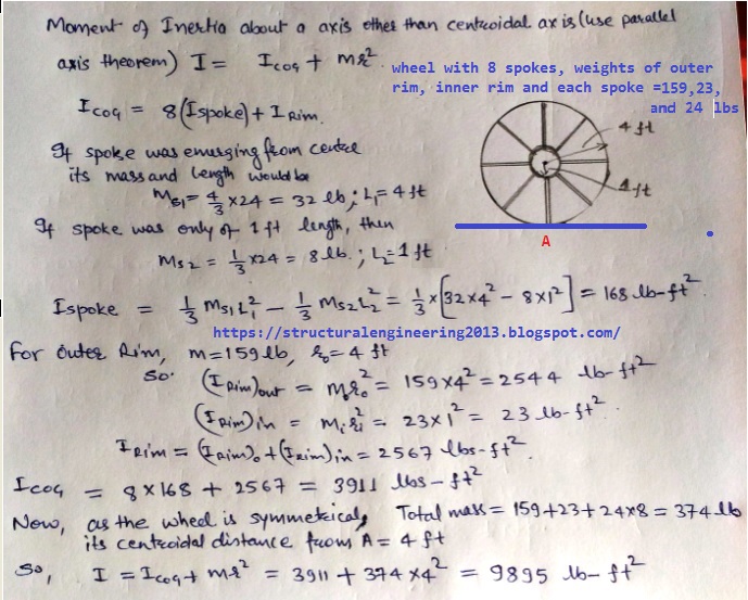
Solved - Moment of Inertia- Spoked Wheel with inner and outer Ring.
Hi,
I was stuck at this problem of finding the mass moment of inertia of a spoked wheel/ring, which is necessary to find out the angular acceleration or the kinetic energy of the wheel.
It's easy to determine the moment of inertia of a spoked wheel with the given weights of the outer rim/ring, inner rim/ring and weight of spokes. The moment of inertia about the centroid and an axis parallel to the centroidal axis can also be easily found. Please refer the image below for knowing the process.

Thanks! please share and subscribe!
I was stuck at this problem of finding the mass moment of inertia of a spoked wheel/ring, which is necessary to find out the angular acceleration or the kinetic energy of the wheel.
It's easy to determine the moment of inertia of a spoked wheel with the given weights of the outer rim/ring, inner rim/ring and weight of spokes. The moment of inertia about the centroid and an axis parallel to the centroidal axis can also be easily found. Please refer the image below for knowing the process.

Thanks! please share and subscribe!
Sunday, July 6, 2014
Flexure Stress and Normal Stress
Hello there,
Its a long time since I have posted in my Structural Engineering blog, so today I thought to discuss something in here. If I ask you the type of stresses, you may come up with the following types:
These are the three types of stresses which we deal all along our structural engineering, arising out of so many different types of loading on the structure. I asked this question to one of my student, if there is any similarity between the first one and the third one.
Normal stress is calculated simply as Force divided by the cross section area under action. Flexure stress is calculated with the help of the flexure formula. Now, to find out the similarility between the two, you have to consider the nature of them.
We know normal stress are either tensile or compressive, similarly, you know that the flexure stresses are also either tensile or compressive.
The main difference between the two, is that the normal stress remains constant throughout the section, but the flexure stress varies along the cross section. This shows that the similarity between the two is that the flexure stresses are also the normal stresses but with a constant variation along the cross section on which applied.
Thanks for your kind visit!
Sunday, June 15, 2014
List of Civil Engineering Softwares used these days
Hi, I was going through the online website of the Autodesk and found a list of the softwares, which caught my interest because many of them are new to me. I have worked with the AutoCad and am little aware of Revit, but there is this huge list of the softwares, titled as given below:
- Building Design suite
- AutoCAD
- Revit
- Simulation Mechanical
- AutoCAD 360
- Buzzsaw
- Robot Structural Analysis Professional
- Vault
- Advance Steel
- Point Layout
- Simulation 360
- AutoCAD LT
- Advance Concrete

License page for downloading the trial versions of Autodesk
Now, if I was in the software industry related with the Civil Engineering projects, hopefully I would have been associated with the other 11 softwares too, but I have ignored them till now. Now that I am thinking of pursuing my M.Tech. in Structural Engineering, I think I should have the knowledge of these softwares.
I think to learn about all these softwares, you need a lot of free time. At the same time, interest matters a lot. If you are interested, you can go the website and try them for free, and if they fulfill your thirst, you can buy them and yes they are very costly.
What do you think, is it important to have the knowledge of every new software product in the market?
Saturday, March 1, 2014
Welding | Design of Steel Structure
Hi,
Welding is a method in which metals are joined together by melting them. This post discusses fillet weld and slot weld, in brief.
Fillet Welds
- Size of fillet weld. It should not be less than the minimum allowable value given in the table in the image above. Size of the fillet weld used along tee of an angle or rounded edge of a flange should not exceed three-forth the nominal thickness of an angle of flange leg.
- Throat of fillet weld. It is length of perpendicular from right angle corner to the hypotenuse.
Value of k depends upon angle between fusion faces. Value of k decreases with increase in angle between fusion face.
In most cases, a right angled fillet weld is used, for which k = 0.7.
- Effective length of fillet weld. It is equal to its overall length minus twice the weld size. Effective length of a fillet weld designed to transmit the loading should not be less than four times weld size. Equal return should be made equal to twice the size of the weld.
- Overlap. Overlap in lap joint should not be less than five times the thickness of the thinner plate as shown in the figure to right.
- Side Fillet. In a lap joint made by a side or longitudinal fillet weld, length of each fillet weld should not be less than perpendicular distance between them; the perpendicular distance between side fillets should not exceed sixteen times thickness of the thinner part connected.
- Intermittent fillet weld. Any section of an intermittent fillet weld should have an effective length of not less than four time the weld size or 40 mm, whichever is greater. Clear spacing between ends or effective lengths of intermittent weld carrying stresses should not exceed 12.t for compression and 16.t for tension and in no case should be more than 20cm, 't; is the thickness of thinner part joined.
- Permissible stress and strength of fillet weld. Permissible stress in fillet weld is 108 MPa or 1100 kgf/cm2.
Slot or Plug Weld
Following specifications are used for the design of slot or Plug welds:
- Width or diameter of slot should not be less than three times the thickness of the part in which slot is formed or 25 mm, whichever is greater.
- Corners at the enclosed ends should be rounded to a radius not less than 1.5 times the thickness of upper plate or 12 mm, whichever is greater.
- Distance between edges of the plates and slot or between edges of adjacent slots should not be less than twice the thickness of the upper plate.
- Permissible stress is taken as 108 MPa or 1100 kgf/cm2.
Thanks!
Monday, January 20, 2014
Two Way Slabs - IS Codes Specification
Hi,
Indian Standard codes give following specification for two way slabs for their analysis.
Bending moment for short span, Mx= Ax.w.Lx^2
Bending moment for long span, My = Ay.w.Ly^2
Where, Ax and Ay are moment co-efficients depending on the ratio Lx/Ly.
Mx = Ax.w.Lx^2
My = Ay.w.Ly^2
Where Ax and Ay are co-efficients depending on the ratio Ly/Lx.
At the corners, top and bottom reinforcement should be provided for torsion.
Thanks for visit!
Indian Standard codes give following specification for two way slabs for their analysis.
- Case 1: Simply supported slabs which do not have adequate provision to resist torsion at corners, and to prevent the corners from lifting.
Bending moment for short span, Mx= Ax.w.Lx^2
Bending moment for long span, My = Ay.w.Ly^2
Where, Ax and Ay are moment co-efficients depending on the ratio Lx/Ly.
- Case 2. Simply supported on the four edges and corners of the slabs are held down.
Mx = Ax.w.Lx^2
My = Ay.w.Ly^2
Where Ax and Ay are co-efficients depending on the ratio Ly/Lx.
At the corners, top and bottom reinforcement should be provided for torsion.
Thanks for visit!
Wednesday, January 8, 2014
Structure Engineering notes for GATE and PSUs - part 13
Hello there,
How have you been!?
How have you been!?
Here is our next part for your preparation for the GATE and PSUs examinations.
All information is learned through books and practical exercises.
- The symmetrical two-hinged parabolic arch when subjected to a uniformly distributed load on the whole span, is subject to normal thrust only.
- In a two-hinged arch, an increase in temperature induces a maximum bending moment at the crown.
- The normal thrust at any section of the arch is the component of interacting forces on the section along the tangent to the centerline of the arch.
- The radial shear at any section of the arch is the component of the interacting forces on the section along the normal to the centerline of the arch.
- The intercept between a given arch and the linear arch at a section is proportional to the bending moment at the section.
- A fixed beam AB is subjected to a triangular load varying from zero at end A to 'w' per unit length at end B. The ratio of fixed end moment at end B to that at end A is 3/2.
- The horizontal thrust due to the rise in temperature in a semi-circular two-hinged arch of radius R is proportional to 1/R2.
Thanks!
Sunday, January 5, 2014
Structure Engineering notes for GATE and PSUs - part 12
Hello there,
How have you been? Here is our next part for your preparation of GATE and PSUs examinations.
All information is learned through books and practical exercises.
- A T-section is used as a simply supported beam with uniform loading. The maximum bending stress for a given load will occur at the bottom of the section.
- Mohr's circle becomes zero when the both the axial stresses are equal in magnitude and of same nature and both planes being free from shear.
- For beams, I-sections are more economical than rectangular sections because most of the material is concentrated away from the centroid.
- The shear stress distribution over a rectangular cross section of a beam follows a parabolic path.
- Shear stress distribution diagram varies for different cross sectional shapes.
- Bending stress distribution diagram is similar for different sections.
- Polar moment of inertia is sum of MI about the XX and YY axes.
- A cantilever beam of uniform EI has span equal to 'L'. An upward force W acts at the mid point of the beam and a downward force P acts at the free end. In order that the deflection at the free end is zero, the relation between P and W should be W=16P/5.
- If K is defined as the ratio of Young's modulus of elasticity and the permissible stress in compression of a material used in the construction of a column, then the Rankine's constant used in finding the load carrying capacity of columns is proportional to 1/K.
Reference:
Thanks for visit!
Subscribe to:
Posts (Atom)