Tuesday, December 31, 2013

Structure Engineering notes for GATE and PSUs - part 8

Hello there,

Are you ready for next part of our preparation notes, for GATE and other PSU examinations?
Here we go:

  • In the displacement method of structure analysis, the basic unknowns are displacements.
  • The fixed supports in a real beam becomes in the conjugate beam a free end.
  • The width of the analogous column in the method of column analogy is 1/EI.
  • The deformation caused by a unit load in a spring is called the flexibility.
  • Conjugate beam can be used to determine slopes and deflection in a non-prismatic beam and gives absolute slope and deflection.
  • In a three hinged arch maximum horizontal thrust occurs when the unit load is at the crown and maximum sagging moment at a section occurs when the unit load is at the section itself.
  • Influence line diagram for the horizontal thrust in a two hinged parabolic arch is cubic.
  • For a single point load W moving on a symmetrical three hinged parabolic arch of span L, the maximum sagging moment occurs at a distance 0.211L from ends.
  • Muller Breslau's principle for obtaining influence lines is applicable to:
  1. trusses
  2. Statically determinate beams and frames
  3. Statically indeterminate structures, the material of which is elastic and obeys Hooke's law.
  • Due to moving loads, the stress in a web member of a truss is given by the influence line for the bending moment for the node point opposite of the member.
  • The stress in a chord member of a truss is given by influence line of shear force for the panel containing the member.
  • In the cantilever method of lateral load analysis, the intensity of axial stress in each column of a storey is proportional to the horizontal distance of that column from the center of gravity of all columns of the storey under consideration.
  • The factor method of analyzing building frames is based upon the slop-deflection method of analysis and is more accurate than either portal or cantilever method.

Thank you for visiting!

Reference: Civil Engineering objectives by S P Gupta and S P Gupta
Monday, December 30, 2013

Structure Engineering notes for GATE and PSUs - part 7

Hello there,
How have you been? Here is our next part for your preparation of GATE and PSUs examinations.


  • A linear arch has normal thrust only, no shear force and no bending moment.
  • A three hinged parabolic arch containing uniformly distributed load is free from the bending moment and shear force.
  • For a determinate pin jointed plane frame, the relation between the number of joints j and members m is given by,  m=2j-3.
  • Triangle is a basic perfect frame.
  • Method of joints is applicable only when the number of unknown forces at the joint under consideration is not more than two.
  • A hollow shaft will transmit more power than a solid shaft of same weight and material.
  • The stiffness of a helical spring is expressed as load per unit deflection.
  • If a rectangular shaft is subjected to torsion, the maximum shear stress occurs at middle of the longer side.
  • If a circular shaft is subjected to a torque T and bending moment M, the ratio of maximum bending stress and maximum shear stress is  2M/T.
  • The radius of gyration of a circle of radius R is equal to  R/2.
  • The ratio of intensity of stress in case of a suddenly applied load to that in case of a gradually applied load is 1.
Thanks for joining in!

Reference: Google & A book "Civil Engineering Objective" by S P Gupta and S P Gupta.

Sunday, December 29, 2013

Structure Engineering notes for GATE and PSUs - part 6

Hello there,

Are you ready for next part of our preparation notes?
Here we go:


  • According to IS:456: 1978, the column or the strut is the member whose effective length is greater than 4 times the least lateral dimenstion.
  • According to IS:456:1978, minimum slenderness ratio for a short column is less than 12.
  • Lap length in compression shall not be less than 24 times diameter of the bar.
  • The minimum cover in slab should neither be less than diameter of the bar nor less than 15 mm.
  • For a longitudinal reinforcing bar in a column, the minimum cover shall neither be less than diameter of the bar nor less than 40 mm.
  • The ratio of the diameter of the reinforcing bars and slab thickness is 1/8.
  • According to IS:456-1978, the maximum reinforcement in a column in a column is 6%.
  • The percentage of reinforcement in case of slabs, when high strength deformed bars are used is not less than 0.12.
  • Minimum cross sectional area of longitudinal reinforcement  in a column is 0.8%.
  • Spacing of longitudinal bars measured along the periphery of column should not exceed 300 mm.
  • Reinforcing bars in columns should not be less than 12 mm.
  • Higher slump and higher compaction factor shows higher workability.
  • Minimum pitch of transverse reinforcement in a column is lesser of 
  1. the lease lateral dimension of the member
  2. Sixteen times the smallest diameter of the longitudinal reinforcement bar to be tied
  3. forty eight times the diameter of the transverse reinforcement.
  • Maximum distance between expansion joints in structures as per IS:456-1978 is 45 m.
  • A continuous beam is deemed to be a deep beam when the ratio of effective span to overall depth (l/D) is less than 2.5.
  • Critical section for shear in case of flat slabs is at a distance of d/2 from the periphery of column/capital/drop panel.
  • Minimum thickness of load bearing RCC wall should be 100 mm.
  • If the storey height is equal to length of RCC wall, the percentage increase in strength is 10.
  • In reinforced concrete footing on soil, the minimum thickness at edge should not be less than 150 mm.
  • The slab is designed as one way if the ratio of long span to short span is greater than 2.
  • Ratio of permissible stress in direct compression and bending compression is less than 1.
  • A higher modular ratio shows a lower compression strength of concrete.
  • The average permissible stress in bond for plain bars in tension is increased by 25% for bars in compression.
  • In working stress design, permissible bond stress in the case of deformed bars is more than that in plain bars by 40%.
  • The main reason for providing numbers of reinforcing bars at a support in a simply supported beam is to resist in that zone the bond stress.

Thanks for visiting!

Bye!

Structure Engineering notes for GATE and PSUs - part 5

Hello there,
How you doing? Here is the useful collection of one liners for the preparation for GATE and PSUs examinations.

  • Intermediate vertical stiffeners in a plate girder need be provided if the depth of web exceeds 85t, where t is the thickness of the web.
  • Bearing stiffeners in a plate girder is used to prevent buckling of web.
  • The forces acting on the web splice of a plate girder are shear and bending forces
  • Gantry girders are designed to resist lateral, longitudinal and vertical loads.
  • Minimum spacing of vertical stiffeners is limited to d/3 where d is the spacing between flange angles.
  • Bearing stiffeners are provided at the supports and at the points of application of concentrated loads.
  • Rivets connected flange angles to cover plates in a plate girder are subjected to horizontal shear only.
  • Maximum spacing of vertical stiffeners is 1.5d, where d is the distance between flange angles.
  • The range of economical spacing of trusses varies from L/3 to L/5.
  • The maximum permissible span of asbestos cement sheets is 1680 mm.
  • Normally, the angle of roof truss with asbestos sheets should not be less than 30 degrees.
  • To minimize the total cost of a roof truss, the ratio of the cost of truss to the cost of purlins shall be 2.
  • Generally the purlins are placed at the panel points so as to avoid  bending moment in rafter.
  • For the buildings having a low permeability, the internal wind pressure acting normal to the wall and roof surface is taken as  +-0.2 p, where p is the basic wind pressure.
  • The relation between intensity of wind pressure p and velocity of wind V is taken as p is directly proportional to V^2.
  • The live load for a sloping roof with slope 15 degree, where access is not provided to roof, is taken as 0.65 kN/m^2.
  • The internal pressure co-efficient on walls for buildings with large permeability is taken as +-0.7.
  • The basic wind speed is specified at a height 'h' above mean ground level in an open terrain. The value of 'h' is  10m.
  • The risk co-efficient k1 depends on mean probable design life of structures and basic wind speed.
  • The external wind pressure acting on a roof depends on slope of roof.
  • Area of openings for buildings of large permeability is more than 20% of the wall area.
  • As per IS: 800, the maximum bending moment for design of purlins can be taken as WL/10, where W is the total distributed load including the wind load on the purlins and L is centre to centre distance of supports.
  • As per IS:875, for the purpose of specifying basic wind velocity, the country has been divided into 6 zones.
  • The numbers of seismic zones into the country has been divided is 5.
  • Minimum pitch provided in riveted steel tanks is 3.0d, where d is the diameter of rivet.

Reference: Civil Engineering objectives by S P Gupta and S P Gupta.
Thanks for joining in!

See ya soon!
bye!

Structure Engineering notes for GATE, PSUs -part 4

Hello there,

Here is another list of one liners which are useful for your preparation of GATE and PSUs exams.


  • A simply supported beam of circular cross-section with diameter d and length l carries a concentrated load W at the center of the beam. The strength of the beam is proportioned to 1/d^3.
  • A cantilever beam carries a uniformly distributed load from fixed end to the center of the beam in the first case and a uniformly distributed load of same intensity from center of the beam to the free end in the second case. The ratio of deflections in the two cases is 7/41
  • If the length of a simply supported beam carrying a concentrated load at the centre is doubled, the deflection at the center will become eight times.
  • A simply supported beam with rectangular cross- section is subjected to a central concentrated load. If the width and depth of the beam are doubled, then the deflection at the center of the beam will be reduced to 6.25%.
  • A laminated spring is given initial curvature because spring becomes flat when it is subjected to design load.
  • A laminated spring is supported at center and loaded at ends.
  • Laminated springs are subjected to bending stresses.
  • Deflection in a leaf spring is more if its stiffness is less.
  • Buckling load for a given column depends upon both length and least lateral dimension.
  • When both ends of a column are fixed, the crippling load is P. If one end of the column is made free, the value of crippling load will be changed to P/16.
  • Euler's formula for a mild steel long column hinged at both ends is not valid for slenderness ratio less than 80.
  • A long column has maximum crippling load when its both ends are fixed.
  • Effective length of a chimney of 20 m height is taken as 40 m.
  • Rankine's formula for column is valid when slenderness ratio has any value.
  • Slenderness ratio of a 5m long column hinged  at both ends and having a circular cross-section with diameter 160 mm is 125.
  • The effect of arching a beam is to reduce bending moment throughout.
  • Internal forces at every cross section in a arch are normal thrust, shear force and bending moment.
  • According to Eddy's theorem, the vertical intercept between the linear arch and the center line of actual arch at any point represents to some scale bending moment in real arch.
  • In a three hinged arch, the linear and actual arch meet at least three points.
  • If a three hinged parabolic arch carries a uniformly distributed load over the entire span, then any section of the arch is subjected to normal thrust only.
Thanks for visiting!

Reference: Civil Engineering Objectives - by S P Gupta and S P Gupta

Saturday, December 28, 2013

Structure Engineering notes for GATE and PSUs - part 3

Hello, How you doing? Here is another post for the preparation of GATE and PSUs exams.


  • The fineness modulus of fine aggregates is in the range of 2.0 to 3.5
  • 1% of voids in concrete mix would reduce its strength by about 5%.
  • Poisson's ratio for concrete increases with richer mixes
  • Finer grading of cement only effects the early strength of the concrete.
  • Factor of safety for steel should be based on its yield strength and that of concrete, on its ultimate strength.
  • The factor of safety for concrete is more than that for steel.
  • For a reinforced concrete section, the shape of shear stress diagram is parabolic above the neutral axis and rectangular below the neutral axis.
  • If a beam fails in bond, then its bond strength can be increased most economically by using thinner bars but more in number.
  • If nominal shear Tv exceeds the design shear strength of concrete Tc,  the nominal shear reinforcement as per IS:456:1978 shall be provided for carrying a shear stress equal to Tv-Tc.
  • Diagonal tension in a beam increases below the neutral axis and decreases above the neutral axis.
  • The individual variation between test strength of sample should not be more than +-15% of average. 
  • According to IS:456:1978 the minimum grade of concrete to be used for RCC is M15.
  • Modulus of elasticity for steel as per IS:456:1978 is 200 KN/mm2.
  • Maximum quantity of water needed per 50 kg of cement for M15 grade of concrete is 32 Liters.
  • In case of hand mixing of concrete, the extra cement to be added is 10%.
  • For walls, columns and all other vertical faces of structural member, the form work is generally removed after 24 hours to 48 hours.
  • If the depth of actual neutral axis in a beam is more than the depth of critical neutral axis then the beam is called over-reinforced beam.


Thanks for visit!

Note: Please leave a comment if you want some specific type of post.

Friday, December 27, 2013

Structure Engineering - notes for GATE, PSUs- part 2

Hello There,
I am in just, to post some one liner statements from steel structure design which, might be helpful to anyone.

  • As per IS: 800, the rivets subjected to combined tensile and shear  stresses are proportioned such as  [fs/ps]+[ft/pt] <= 1.4
  • According to IS specifications, the maximum pitch of rivets in compression is lesser of 200 mm and 12t.
  • A circular column section is generally not used in actual practice because it is difficult to connect beam to round sections.
  • The slenderness ratio of a column supported throughout its length by masonry wall  is zero.
  • According to IS specifications, the effective length of a column effectively held in position at both ends and restrained in direction at one end is taken as 0.8L.
  • The effective length of a battened strut effectively held in position at both ends but not restrained in direction is taken as 1.1L.
  • The maximum slenderness ratio of a compression member carrying both dead load and live load is 180.
  • The maximum slenderness ratio of a steel column design of which is governed by wind or seismic forces is 250.
  • According to IS:800, in the merchant - Rankine formula the value of imperfection index(n) is 1.4
  • If 20mm rivets are used in lacing bars, then the minimum width of lacing bar should be 60mm.

Thanks for visiting!

Reference: Civil Engineering Objectives - S P Gupta and S P Gupta

Tuesday, December 24, 2013

Structural Engineering notes for GATE, PSUs - part 1

Hello, How you doing?


 I just picked following information for the structural Engineers, I hope this is useful:


  • Minimum 4 Nos. of bars for rectangular columns and 6 Nos. for circular columns are to be used.
  • Lapping is not allowed for the bars having diameter more than 36 mm.
  •  For chairs minimum 12 mm diameter bars are to be used.
  • For dowel minimum of 12 diameter bars should be used.
  • Main bars in slab shall not be less than 8 mm (HYSD) diameter and 10 mm (Plain bars) diameters.
  • Longitudinal reinforcement should not be less than 0.8% and not more than 6% of the gross C/S.
  • Minimum thickness of slab is 125 mm.
  •  A maximum of 1.5 m of free fall is allowed for concrete pouring.
  • pH value of water used shall not be less than 6.
  • In steel reinforcement 8 kg of winding wire is required per MT.


Please contribute to improve the article and,

Thanks for visiting!

Monday, December 23, 2013

Structure Engineering MCQs

Hello, How you doing?


The solutions are given at the bottom.

  1. Choose the right one:
    A fixed beam is
    • (A) Determinate Structure
    • (B) Un-Stable
    • (C) Indeterminate Structure
    • (D) None of the above

  2. When we provide a hinge in a structure, the numbers of equations of static equilibrium increase by:
    • (A) 2
    • (B) 1
    • (C) 3
    • (D) 4

  3. Shape Factor Depends upon:
    • (A) Length of the Beam
    • (B) Cross sectional dimensions
    • (C) Magnitude of applied load
    • (D)  Types of supports

  4. The effect of arching a beam is:
    • (A) Reduce Shear stress
    • (B) Reduce Bending moment
    • (C) Increase the shear force
    • (D) Increase the bending moment

  5. Simplest form of a perfect frame is
    • (A) Rectangle
    • (B) Square
    • (C) Triangle
    • (D) Pentagon
  6. Size of a fillet weld is:
    • (A) Throat Thickness
    • (B) Longer Side
    • (C) Shorter side
    • (D) Average of longer and shorter side.

  7. Which of the following section is not preferred in case of beam design?
    • (A) Over-reinforced section
    • (B) Under-reinforced section
    • (C) Balanced section


Answers:

  1. C
  2. B
  3. B
  4. B
  5. C
  6. C
  7. A


Please contribute to improve the article,

Thanks for visiting!

Wednesday, December 18, 2013

Simple Theory of Bending

Hello,

The main basic study which is important for the design of the structures is the "Strength of materials". Theory of Simple Bending is the theory which must be understood to be an effective structural engineer.

This theory studies the bending of the structural elements and gives us the nature and the magnitude of the induced stresses in the structure due to the applied bending moment.

There are some assumptions:
(1) The material is elastic and homogeneous.
(2) The material obeys Hook's law
(3) Plane sections remain plane after bending.
These are some of the most important assumption now, let's go to the theory part.

According to this theory when a structural element let's take a beam,  is applied with the bending moment, it bends into the circular shape.  Every section will have the stress variation from the top to the bottom of the section.

The stresses varies linearly along the depth of the section and so does the strain. When sagging moment is applied to the beam the stresses are compressive on the top of the neutral axis and are tensile on the bottom of the neutral axis.

bending stresses are zero at the neutral axis. The variation of the stresses is linear along the depth, maximum at the extreme layers and zero at the center, and of opposite nature on the two sides of the neutral axis.

When the sections is analyzed for the magnitude of the stresses and its variation along the depth, theory gives us a very important formula, known as the "Flexure Formula".

M/I = f/y = E/R

Where, M = Bending moment at the section
            I = Moment of inertia of the section about an axis perpendicular to the applied loads.
            f = flexural stress/bending stress at a distance 'y' from the neutral axis.
            E= Thomas Young's modulus of Elasticity.
            R= Radius of the curved beam/ elastic curve of deflection.

Thank you for reading!

Saturday, December 14, 2013

Plastic Theory of structure analysis- A short introduction

Hello, 
How are you doing!?

Here is a brief introduction to the plastic Theory of structure analysis.


  • Plastic Theory of structural analysis:

Any ductile material like steel, after reaching the yield point undergoes plastic strain. After following a certain path the stress strain curve will end up at a certain distance from the yield point.
This path of the curve is known as the plastic region of the stress strain curve.
The highest stress value before reaching the rupture is known as the ultimate strength of the material.

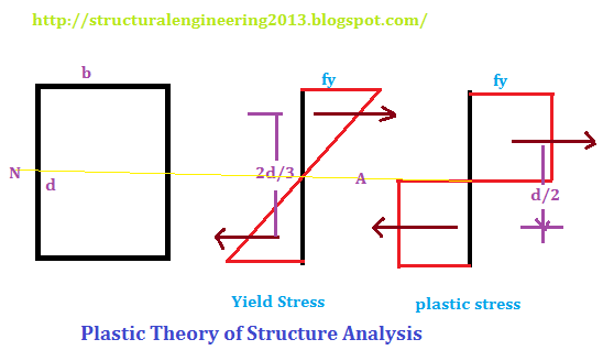
In simple theory of bending, we assume that stress and strain vary linearly along the cross section of the steel along its depth. Stress is zero at the neutral axis and maximum at the extreme fibers.

After the stress reaches the yield point the extreme fibers will not take any further stress but the internal fibers still have not reached the yield stress so, the plastic strain will start when the every layer reaches the yield stress.


Plastic Theory of Structural Analysis

This produces another stress diagram which is shown in the figure above(first from right). For the third diagram the moment of resistance is calculated which is known as the plastic moment of resistance. 

  • Load Factor: The ratio of the plastic moment of resistance to the working moment of resistance is known as the load factor. For a rectangular cross section beam this value comes out to be 1.5(fy/fb). So, if fy/fb = 1.5, then Load factor = 2.5


  • Shape Factor: The ratio of the plastic moment to the yield moment is known as the Shape factor. Mp/My is known as shape factor. It may be remembered that shape factor is the property of a section which depends only upon the geometry of the cross section.


  • Collapse Load:

Once the section reaches the plastic stage, it acts likes a plastic hinge. So, to analyse a structure we have to form the plastic hinges at the place where bending moment takes up the maximum values. These hinges take up the moment equal to plastic moment and after that they will collapse. 

The theory behind the analysis of the collapse load is very simple. The external work done is equal to the internal work done. That means collapse load multiplied by the corresponding displacement is equal to the plastic moment multiplied by the respective rotation of the joints. 

It will not be possible to show here an example to you so, let's keep that to future.

Thank you for visit.

Friday, December 13, 2013

Conjugate Beam Method of Slope and Deflection

Hello, 
How you doing?


I was surfing through a Facebook page and I found that people are confused with this method, so I thought to put it on my blog. You can follow my page on Facebook:
https://www.facebook.com/Structengineers

Back to topic, I will put this in very simple words, for details please leave a comment in the comment box.


  • What is conjugate beam?

Conjugate beam is an imaginary beam which has the same length as that of the original beam and has the same supports but has different loading. Loading for the conjugate beam at any point is the bending moment diagram for the original beam divided by "EI" i.e. flexural rigidity of the beam. In short the loading for the conjugate beam is M/EI diagram of the original beam.
Conjugate Beam


  • Slope at a point using conjugate beam:

Now as you have drawn the conjugate beam, to find out the slope at any point on the beam, simply find out the shear force at that point for the conjugate beam, that is it.


  • Deflection at a point using conjugate beam:


Similarly to find out the deflection at a given point, you have to find out the bending moment at that point in the conjugate beam.  It is as simple as explained.

Note : Please  help to improve the article.
Thanks for visiting!

Wednesday, December 11, 2013

Gantry Girders

Hello,

Gantry Girders: Introduction

Gantry girders are used in the factories, where the loads are transferred from one place to another with the helps of cranes mounted on the bridges. Bridges across the yards are supported by the gantry girders with the help of the wheels and rails on the girders. Bridges can move along the gantry girder and more than one bridges can also be there on a gantry girder.
Gantry girders

Gantry girders generally are composed of the rolled steel sections. They may be composed of more than one section, like channels and beams together.

To design a gantry girder, we have  to find out the maximum bending moment which will occur on the gantry girder, due to external loads, and its own self weight.

As we know that absolute maximum bending moment for a simply supported girder will occur at the center, the central section are designed accordingly and the sections at the ends may be curtailed.

Curtailing the ends means cutting the section along the flanges, for making the design economic.

thanks for your kind visit! 

Monday, December 9, 2013

Plate Girders

Image source: Wikipedia
Introduction:
Plate girders are generally used in the plate girder bridges.
These are used when standard rolled sections do not provide the required section modulus. The image on the left shows a plate girder bridge. Building up a beam by riveting plates and angles increase the modulus of section. Plate girders are adopted specifically for short spans and heavy loads.
James Millholland built first tubular, wrought iron plate girder in  1846-47.

Components in a riveted plate girder:
a) web and Flange plates.
b) Flange angles.
c) Stiffeners
d) Splices.

Design of web and flange plates:
Web and flange plates are the main components of a plate girder and are designed to resist the shear and bending respectively.

(a) depth of Girders:
Approximate depth of girder is usually taken as 1/8 to 1/2 of the effective span of the girder.

(b) Width of flange: Width of flange would be within a range of L/40 to L/45.

(c) Deflection: Maximum deflection should not exceed 1/325 of the span.


Plate girder, source : wikipedia
Allowable Stresses: 

Upto 20mm web thickness :
 Bending stress = 1575 kg/cm2
Shear Stress = 945 kg/cm2

Over 20 mm thick web : Bending stress = 1500 kg/cm2 ; Shear Stress = 865 kg/cm2

Minimum thickness of the plates: Fr girders exposed to weather but accessible for painting, it is 6 mm; For girders exposed to weather but not accessible for painting, it is 8mm.


References:
1.Wikipedia
2. GATE 2013 civil Engineering - GK Publishers

Sunday, December 8, 2013

Structure Analysis - II - HPTU 2012 question paper

HI,
Following are the four pages of the end semester, SA- II (CE-5001) , HPTU, question paper, which you can download and use for your reference.
Thanks.